EcoMAX 613, 618, 622, 635, 824, 828 and 835 Condensing Boilers
Quick Fault Finding Procedure
When troubleshooting your Vaillant EcoMAX boiler please follow the following logical fault finding procedure:
- Electrical Safety Checks. Check the electrical circuits by testing short circuit, earth continuity and resistance to earth tests. Check correct electrical polarity.
- Electrical Supply. Ensure that the boiler has electrical supply correct to 230 V.
- Gas Supply. Check the boiler has gas supply and that it has been purged. Ensure the boiler has an inlet gas pressure of 20 mbar at the gas valve.
Warning: Use only qualified CORGI registered contractors to work on gas boilers.
- Filling the Heating system. Ensure that the boiler is full of water and charged to 1-1.5 BAR.
- Control. Ensure main on/off control is set to ‘on’
- Temperature. Set the heating temperature to the maximum setting.
- External Controls. Check that the external control display is calling for heat. Ensure that the boiler’s anti-cycling economiser is not engaging.
Checking Status Mode
By checking the status mode you are checking the operation status of your boiler. To check the status mode press the information button designated ‘i’ on your display, and a code will appear indicating the operational status of the boiler. The information on the status codes and what they mean check the table below:
| Code | Code Meaning | Notes |
| S.0 | No Heat Demand | Heating Operation |
| S.1 | Pump Running | Heating Operation |
| S.2 | Pump Running Prior to Ignition | Heating Operation |
| S.3 | Ignition Sequence | Heating Operation |
| S.4 | Burner Ignited | Heating Operation |
| S.6 | Heating System Fan Overrun | |
| S.7 | Pump Over Run | Heating Operation |
| S.8 | Anti Cycling Mode | Heating Operation |
| S.10 | Hot Water Demand | Hot Water Operation |
| S.11 | Pump and Fan Running | Hot Water Operation |
| S.13 | Ignition Sequence | Hot Water Operation |
| S.14 | Burner Ignited | Hot Water Operation |
| S.16 | Fan Overrun | Hot Water Operation |
| S.17 | Pump Overrun | Hot Water Operation |
| S.20 | Warmstart Demand | Warm Start |
| S.21 | Pump and Fan Running | Warm Start |
| S.23 | Ignition Sequence | Warm Start |
| S.23 | Burner Ignited | Warm Start |
| S.26 | Hot-Water Fan Overrun | |
| S.27 | Pump Overrun | Warm Start |
| S.28 | Anti Cycling Mode | Warm Start |
| S.30 | No Heating Demand from External Controls | |
| S.32 | Fan Unit Waiting Period | |
| S.34 | Frost Proctection Mode | |
| S.36 | No Heating Demand from Low Voltage Controls | |
| S.37 | Fan Unit Waiting Period | |
| S.39 | Contact Thermostat has been activated | Under Floor Systems |
| S.53 | Delay Mode due to lack of water in system | 20 mins |
| S.54 | Low Level Water Waiting Period |
Checking Diagnosis Codes
By checking the Diagnosis Codes you are able to find the particular fault that your boiler is experiencing. This will give you the information to troubleshoot and conduct the necessary changes or repair to your system. To check the diagnosis mode press the information button ‘I’ and ‘+’ simultaneously and you should see ‘d.0’ in the display. Scroll with the ‘+’ or ‘-‘ keys up or down to the required diagnostic number. When you have arrived at your desired code press the ‘I’ button to interrogate the system. You can also alter the value by pressing ‘+’ or ‘-‘ keys. The values will flash when altering, and to save press and hold the information button ‘i’
For information of what each diagnostic code is refer to the table below:
| Code | Diagnosis Code Meaning | Display | Notes |
| d.0 | Part Load Setting | Adustable Values in KW | |
| d.1 | Water Pump Overrun | 1 - 60 min | Factory Adjusted to 5 minutes |
| d.2 | Maximum Burner anti cycling period at 20¡C flow temperature | 2 - 60 min | Factory Adjusted to 20 minutes |
| d.5 | Flow Temperature Setting | °C | |
| d.7 | Warmstart Temperature Setting | °C | EcoMAX 800 only |
| d.8 | External Controls Heat Demand | 0 = Room Thermostat open (No Demand) 1 = Room Thermostat Closed (Demand) | |
| d.10 | Pump Status | 1 = ON 2 = OFF | |
| d.13 | External Pump Status | 1 = ON 2 = OFF | |
| d.14 | External Circulation Pump when fitted | 1 = ON 2 = OFF | EcoMAX 835 Only |
| d.16 | Pump Speed | Set Value for Built-in Pump 0 = auto 1 = 53% 2 = 60% 3 = 70% 4 = 85% 5 = 100% | EcoMAX 635, 835 Only |
| d.22 | Second Pump | 1 = DHW Circulating Pump 2 = External CH Pump 3 = Vantage Loading Pump 4 = Solar Pump | |
| d.23 | Summer/Winter Function | 1 = WINTER 2 = SUMMER | Control Knob |
| d.25 | Hot-water activation via warm-start clock | 1 = YES 2 = NO | |
| d.34 | Current Fan Speed Valve | rpm/10 | |
| d.35 | Diverter Valve Position | 0 = Heating system 1 = Hot Water 2 = Mid Position | EcoMAX 800 Only |
| d.40 | Actual Flow Temperature | °C | |
| d.41 | Actual Return Temperature | °C | |
| d.44 | Actual Ionisation Current Value | Divide by 100 in Amps | |
| d.46 | Outside Temperature Correction | K | |
| d.47 | Actual Outside Temperature | °C | |
| d.60 | Number Over Heat Cut Off Operations | Number | |
| d.61 | Number of Lock Outs | Number | Number of unsuccessfull ignition operations at last attempt |
| d.67 | Remaining Anti Cycling Periods | Minutes | |
| d.68 | No First Start | Number | Number of unsuccessfull 1st ignition |
| d.69 | No Second Start | Number | Number of unsuccessfull 2nd ignition |
| d.71 | Maximum Target Value for Heating System | 40 - 85°C | Maximum target value for heating system flow temperature |
| d.72 | Pump Overrun | Seconds | Pump overrun period after filling of an electronically controlled hot water tank |
| d.73 | Offset Warmstart Temperature Value | -15K to +15K | Factory adjusted to -5K. Recommended Setting for Solar applications 7°C EcoMAX 800 Only. |
| d.80 | Number of Heating System Operating Hours | Hours | |
| d.81 | Number of Hot Water System Operating Hours | Hours | |
| d.82 | Number of Heating System Cycles (Total) | Number | |
| d.83 | Number of Hot Water System Cycles (Total) | Number |
Checking Fault Codes
Fault codes only display if your system experiences one of the registered faults. These fault codes will display in priority to all other information on the display. Generally speaking if you have an issue with your boiler you will have some form of fault code displaying automatically. If you do not then refer to the diagnosis codes above. If you have multiple faults then the corresponding fault code s will alternate display every 2 seconds. The system will record the last 10 fault codes, so to see each one press the ‘+’ and‘-‘ keys simultaneously then scroll with the ‘+’ key. To cancel the fault error memory press and hold the ‘i’ key.
For information on each fault code refer to the table below:
| Code | Fault Code Meaning | Cause |
| F.0 | Flow-NTC | Flow-NTC cable defective or broken |
| F.1 | Return-NTC | Flow-NTC cable defective or broken |
| F.10 | Short circuit - Flow NTC | NTC plug shorted to casing, NTC Defective |
| F.11 | Short Circuit - Return NTC | NTC plug shorted to casing |
| F.13 | Short circuit in Tank Sensor | NTC Defective, dhort circuit in cable loom, damp plug connection |
| F.20 | Over Heat Cut Off Activated | Maximum Temperature Exceeded |
| F.22 | Low Water or No Water | No Water in System, Pump Defective or Pump Lead Defective |
| F.23 | Water Temperature Low. Temperature Range too Wide | Pump Obstructed, pump running at low capacity, air in applicance, system pressure too low, flow and backflow NTC reversed |
| F.24 | Water Temperature Low. Temperature Range too Fast | Pump Obstructed, pump running at low capacity, air in applicance, system pressure too low, flow and backflow NTC reversed |
| F.25 | Water Switch. System Pressure Too Low | Pump Obstructed, pump running at low capacity, air in applicance, system pressure too low, flow and backflow NTC reversed |
| F.27 | No Demand to Gas Valve | Electronic Board Defective, Gas Valve Defective |
| F.28 | Boiler Goes To Lock Out | No Gas, Insufficient gas, Incorrect gas valve adjustment, electrode defective, ignition lead defective, electronic ignitor defective or check air inlet duct |
| F.29 | Flame Extinguished re-ignition unsuccessfull | Gas supply or Check Flue Duct |
| F.32 | Fan Turning speed Malfunction | Fan Unit Obstructed, plug-in fan connector not correctly inserted, hall sensor defective, fault in cable loom or defective electronic control system |
| F.60 | Gas valve control + defective | Short Circuit in cable loom to gas valves, gas valve assembly defective or electronic control system defective |
| F.61 | Gas valve control - defective | Short Circuit in cable loom to gas valves, gas valve assembly defective or electronic control system defective |
| F.62 | Defective gas valve closure mechanism | Leak in gas valve assembly or electronic falut |
| F.63 | EEPROM error | Electronic Falut |
| F.64 | Electronic System/sensor Fault | Short Circuit in flow or backflow NTC or Electronic fault |
| F.65 | Electronic system Temperature too high | Electronic System Affected by external heat source or electronic fault |
| F.67 | Electronic fault in flame system | Electronic fault |
Run a Test Program
By running a test program allows the sequential activation of special functions to test your boiler. The test programs are activated by pressing the Power ‘ON’ switch and ‘+’ simultaneously for 5 seconds. By default ‘P.1’ will display, where you can scroll by pressing the ‘+’ button. Press the ‘I’ button to start the unit and test the selected program. A test program can be aborted at any time by pressing the ‘I’ and ‘+’ buttons simultaneously.
For information on each Test Program refer to the table below:
| Code | Test Program Meaning |
| P.1 | Test Program used when the unit runs at full load after successful ignition |
| P.2 | Test program used when the unit runs with minimum gas consumption after successful ignition |
| P.5 | Program for STB (Safety Temperature Limiter) testing; the device heats up, bypassing the regular shutdown procedure, until it reaches the STB shutdown temperature of 97¡C |
Parts Replacement
Safety First!
Please Note: Use only qualified CORGI registered contractors to work on gas boilers.
- Isolate Mains power to your boiler system by either removing the electrical plug at the socket or switching the breaker off or removing the fuse at the breaker/fuse box.
- Turn off gas supply to your boiler
- When removing any items containing water (Hoses, pipes etc) make sure they do not spill on electrical components
- Always replace consumable parts like o-rings and gaskets with new parts
- Always test for gas and undertake functional checks of the boiler after doing work to gas carrying components
- Always conduct electrical check such as polarity, continuity and resistance to earth with a multimeter before and after any work
Initial Steps
- Turn off the boiler
- Isolate electric supply to your boiler
- Remove the boiler’s bottom cover
- Turn off the gas supply
- Turn off the CH valves
- Turn off the cold water inlet valves (EcoMAX 800 series)
- Remove the front cover
- Carefully lower the electronic control box
- Drain the central heating via the drain points to drop the boiler’s water pressure
Removal of Burner
- Remove the screw connecting the air inlet pipe
- Disconnect the gas valve union
- Disconnect the HT lead and earth lead from spark electrode
- Remove the burner manifold by undoing the five nuts
- Disconnect the fan and gas valve
- Retrieve the complete burner assembly including burner, gas valve and fan
- Remove the burner, gas valve and fan from the boiler.
Replacement of Burner
- Turn off the boiler
- Remove the front casing
- Lower the control box
- Remove the burner, gas valve and fan
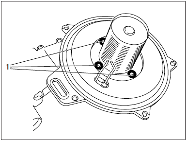
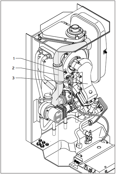
- Remove the four screws shown in (1) above, fixing the burner to the burner manifold
- Affix the new burner to the manifold using a new sealing gasket (usually supplied with the new burner), ensuring that the notch in the burner aligns with the burner-viewing window
- Reassembly in the reverse order to above
- Recommission the boiler as per procedure
Replacement of Fan
- Turn off boiler
- Remove the front panel
- Gently lower the control box
- Remove the burner, gas valve and fan assembly
- Remove the four screws shown in (1) above
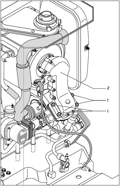
- Separate the gas valve and fan assembly from the burner manifold (2) above
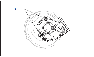
- Remove the two screws (3) above, securing the gas valve to the fan
- Affix the gas valve to the fan to burner manifold using the new sealing gasket which is supplied. Tighten the four screws equally to maintain a good seal.
- Reassembly the entire assembly in reverse order
- Recommission boiler as per procedure
Replacement of Gas Valve
- Turn off boiler
- Remove the front panel
- Gently lower the control box
- Remove the burner, gas valve and fan assembly
- Remove the four screws shown in (1) above
- Separate the gas valve and fan assembly from the burner manifold (2) above
- Remove the two screws (3) above, securing the gas valve to the fan
- Disconnect the gas inlet supply to the gas valve by removing the four screws, and change out with a new gas valve using the new sealing gasket supplied
- Refit the gas valve and fan assembly to the burner manifold using the new sealing gasket. Tighten all four screws equally to ensure good seal.
- Reassembly the entire assembly in reverse order
- Recommission boiler as per procedure. Ensure a combustion analysis is conducted.
Replacement of Central Heating Expansion Vessel
- Turn off boiler
- Remove the front panel
- Gently lower the control box
- Drain the boiler
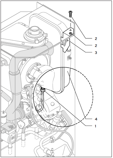
- Remove the union shown (1) above from the expansion vessel
- Remove two screws shown in (2) above and remove the retaining bracket shown as (3) above
- Slide the expansion vessel forward to remove it from the boiler
- Reassembly the entire assembly in reverse order
- Recommission boiler as per procedure
Replacement of Central Heating Expansion Vessel
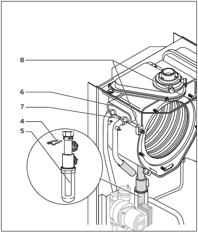
- Turn off the boiler
- Remove the front panel
- Gently lower the control box
- Drain the boiler
- Remove the burner, gas valve and fan assembly as above
- Disconnect the condensate drain by removing the clip shown (4) above, and pulling the condensate drain down shown (5) downwards
- Remove the primary flow connection shown (7) from the heat exchanger
- Disconnect the primary return connection shown (6) from the heat exchanger
- Loosen the nylon nut at the bottom of the heat exchanger
- Loosen the two top securing bolts shown (8) and roate the clamps away from the heat exchanger
- Remove the bottom screw and securing clamp shown (8)
- Pull heat exchanger forward and remove from the boiler
- Drain any water from the heat exchanger
- Reassembly the entire assembly in reverse order
- Recommission boiler as per procedure
Replacement of Electronic Control Board
- Turn off the boiler
- Remove the front panel
- Gently lower the control box
- Unclip the back cover from the electronics box and open the cover
- Unclip the front cover and remove the cover
- Disconnect all the wires to the board
- Unclip and remove the circuit board
- Remove the display unit and timer (if fitted)
- Clip the new circuit board in position, reconnect all the wires and refit the covers
- Raise the unit and reinstall the display unit and timer (if fitted)
- Recommission boiler as per procedure
The new circuit board must be adapted to the heating unit, therefore follow the instruction in the table below.
| Code | Description | Displayed Values | Circuit Board Setting | Setting for EcoMAX 600 series | Setting for EcoMAX 800 series | Comments |
| d.0 | Heating System Part Load | Adjustable values in KW | 45 kW | system dependent | system dependent | MUST be adjusted when new |
| d.1 | Heating System Pump Overrun | 1-60min | 5 min | system dependent | system dependent | May be adjusted |
| d.2 | Heating system max. off-period | 1-60min | 20 min | system dependent | system dependent | May be adjusted |
| d.14 | Pump speed | Set value for built in pump 0(auto), 53, 60, 70, 85, 100 % | 0 (Auto) | system dependent | system dependent | May be adjusted |
| d.16 | External CH pump | 1, 2, 3, or 4 | 1 | N/A | 2 | May be adjusted |
| d.71 | Max. target value for heating system flow temperature | 40 - 85¡C | 82¡C | system dependent | system dependent | May be adjusted |
| d.72 | Hot-water pump overrun | 0 - 250 s | 80 s | system dependent | system dependent | May be adjusted |
| d.73 | Difference between warm start and hot-water outlet target value | -15 K to +15 K | -9 K | N/A | N/A | MUST be adjusted when new |